

A Heavy Duty Hydraulic Press converts fluid pressure into controlled mechanical force. It can compress, bend, shape, straighten, or assemble demanding industrial components. Its steel frame supports a hydraulic cylinder, ram, work table, and pressure-control system. Inside the cylinder, pressurized oil moves a piston. The piston then drives the ram downward or upward.
The operating principle is based on Pascal’s law. Pressure applied to a confined fluid spreads throughout that fluid. A small pump force can therefore create much greater force at the ram. The result depends on cylinder area, pump capacity, pressure settings, and machine design. A pressure gauge shows the operator what is happening. It does not replace careful judgment.
Real-world performance depends on more than specifications. Experienced technicians inspect hoses, seals, guards, and alignment before pressing material. They also listen for unusual pump noise and watch for unstable movement. A clean work area matters. So does correct tooling. Poorly supported material can shift suddenly, even when the machine appears solid.
This guide explains the main components, working cycle, applications, and maintenance needs of a Heavy Duty Hydraulic Press. It also considers practical limits. More force is not always better. Excessive pressure can damage tooling, deform parts, or overload the frame. No machine is risk-free. Some explanations may simplify complex hydraulic behavior, because actual performance varies between models, materials, and operating conditions. Reliable results require the manufacturer’s instructions, trained operation, and regular inspection.
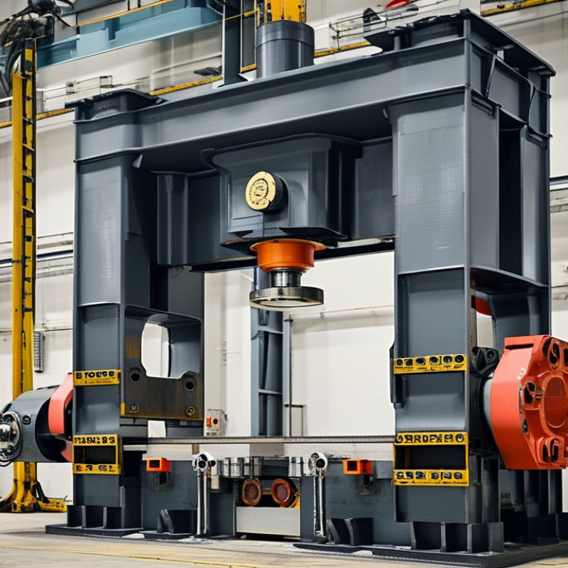
A heavy-duty hydraulic press is an industrial machine that uses confined fluid to create controlled compressive force. Its core purpose is simple: shape, form, join, straighten, or separate tough materials with repeatable pressure. Unlike a light workshop press, it handles higher loads, larger workpieces, and longer production cycles. The frame carries the load. A hydraulic cylinder delivers movement. A pump, reservoir, valves, and pressure controls manage the fluid. The working table supports the material and tooling. These parts must work together. A strong cylinder alone is not enough.
The machine operates through Pascal’s law: pressure applied to enclosed hydraulic fluid spreads evenly in every direction. A pump sends hydraulic fluid into the cylinder, pushing a piston downward or upward. The piston transfers force through a ram to a die, platen, or fitted tool. Because force depends on pressure and piston area, a relatively compact system can generate enormous pressing power. Operators set pressure, stroke, speed, and dwell time according to the job. Sensors and relief valves help prevent overloads. Still, settings require judgment. Material thickness, temperature, alignment, and tool condition can change the result.
In daily industrial use, the press may compact metal components, bend plates, form parts, or remove tightly fitted bearings. It can apply force gradually, reducing sudden impact and improving process control. Heavy-duty does not mean universally better. An oversized press can waste energy and make delicate work harder. Poor alignment may damage tooling or produce uneven parts. Regular inspections matter, especially around hoses, seals, guards, and pressure connections. Experienced technicians verify the load path before pressing, because a small setup error can become a serious mechanical problem.

A heavy duty hydraulic press uses confined fluid to produce controlled force. Its rigid frame supports the load and resists bending during operation. The hydraulic cylinder contains a piston and converts fluid pressure into straight-line movement. When oil enters the cylinder, the piston moves downward or upward.
The pump supplies pressurized fluid from the reservoir. Valves direct that fluid, control movement, and release pressure when the cycle ends. A pressure gauge helps operators monitor force, although gauges can drift if maintenance is neglected. The press bed supports the workpiece, while adjustable tooling sets the forming or compressing position. Modern systems may also include limit switches, guards, and emergency stops. These parts reduce exposure to crushing hazards, but they do not replace trained operation. In my experience, alignment is often overlooked. A slightly tilted workpiece can create uneven loading and damage both tooling and the frame.
Tips: Check hoses, fittings, and fluid levels before each shift. Keep the workpiece centered on the bed. Increase pressure gradually, not suddenly. Stop immediately if the frame flexes, the gauge behaves strangely, or the cylinder moves unevenly. A clean work area matters. Small metal fragments can affect alignment and become dangerous projectiles. Follow the equipment’s rated capacity, because “heavy duty” does not mean unlimited force. Record inspections and pressure readings. This simple habit can reveal wear before a failure occurs.
A heavy-duty hydraulic press converts fluid pressure into controlled mechanical force. Its pump pushes oil through a valve into a cylinder. Pressure acts on the piston area, following the relationship F = P × A. For example, 25 MPa applied to a 0.02 m² piston produces about 500,000 newtons, equal to roughly 51 metric tons of force.
That is substantial.
The National Fluid Power Association’s 2024 U.S. Fluid Power Industry Statistical Report identifies hydraulic equipment as a major industrial power-transmission sector. Its data reflects continued demand for high-force systems in forming, recycling, and metal fabrication. In practice, a press operator may set 250 bar, but the actual force still depends on piston diameter, friction, oil temperature, and leakage. A larger cylinder generates more force at the same pressure. However, it moves more slowly and requires greater oil volume.
ISO 4413 emphasizes pressure control, filtration, guarding, and safe energy isolation for hydraulic systems. These details matter because compressed oil stores dangerous energy. A relief valve limits excessive pressure, while directional valves control extension and return. Field experience also shows a less obvious problem: a clean pressure gauge does not prove the cylinder is healthy. Internal seal wear can reduce holding force without obvious external leakage. Calculations are essential, but real machines sometimes behave differently. That gap deserves inspection, not guesswork.
This chart shows the theoretical force produced by a hydraulic cylinder with a piston area of 100 cm². Force is calculated using F = P × A. At this fixed piston area, every additional 50 bar of hydraulic pressure increases the output force by approximately 50 kN. Actual heavy-duty press force may be lower because of friction, leakage, and mechanical losses.
A heavy-duty hydraulic press converts fluid pressure into controlled forming force. The basic relation is simple: force equals pressure multiplied by piston area. In practice, the pressing cycle demands far more discipline. World Steel Association data recorded about 1.89 billion tonnes of crude steel production in 2023. That volume supports constant demand for reliable forming, bending, and straightening equipment.
The process begins with a pre-use inspection. The operator checks guards, hoses, seals, oil level, and emergency controls. The workpiece must sit squarely on the lower bed. A small alignment error can create uneven loading. The controller then starts the pump and builds pressure gradually. Sensors track ram position, pressure, and cycle time. When the ram reaches the programmed approach point, the system slows down before contact. This reduces impact and protects the tooling.
During pressing, the control system holds force within a defined range. It may pause for material flow, then release pressure in stages. Operators watch for vibration, leakage, unusual noise, or sudden pressure loss. ISO 4413 emphasizes risk control for hydraulic systems, including safe pressure release and stored-energy management. The sequence sounds tidy, but real production is not. A slightly dirty filter can distort response. A worn seal can change results between cycles. Data logging helps, although a sensor reading is not always the whole truth. Experienced technicians compare measurements with the actual part, surface marks, and machine behavior.
A heavy-duty hydraulic press uses fluid pressure to move a large cylinder. A pump sends hydraulic fluid through controlled valves. The fluid pushes a piston against a workpiece. Force depends on pressure and piston area, not speed alone. In industrial settings, the frame may handle thousands of kilonewtons. Steel plates, shafts, bearings, and formed components commonly meet this machine.
Manufacturers use presses for deep drawing, bending, stamping, straightening, compacting, and assembly. They shape thick steel with steady, measurable force. This control can reduce cracking and improve repeatability. A press also supports repair work, such as removing a seized bearing. Cycle time may be slower than some mechanical systems. However, adjustable pressure and stroke can protect delicate parts. Energy efficiency depends on pump design, idle time, and maintenance.
Safety begins before the ram moves. Operators should inspect hoses, fittings, guards, tooling, and emergency stops. The die must sit squarely, with no loose spacers or unstable supports. Keep hands outside the danger zone. Use rated tooling and verify the load chart. Never exceed pressure limits. Leaking fluid can penetrate skin through a tiny pinhole. Stop, isolate, and depressurize the system before adjustment or cleaning. Training matters. So does honest reporting. A rushed setup can defeat an excellent safety procedure. Regular records, competent inspections, and site-specific risk assessments help reveal failures before injuries occur.
| Category | Data Dimension | Typical Value or Technical Reference | How It Works or Where It Is Used | Safety and Operating Considerations |
|---|---|---|---|---|
| Definition | Primary operating principle | Pascal’s law | Pressure applied to an enclosed hydraulic fluid is transmitted throughout the fluid, allowing a relatively small input force to produce a much larger output force. | Hydraulic circuits must be designed for the maximum rated pressure, including pressure spikes and blocked-flow conditions. |
| Capacity | Rated pressing force | Approximately 100 to more than 10,000 metric tonnes, depending on machine design | Force capacity is selected according to material strength, part geometry, tooling requirements, and the required forming or straightening load. | Never exceed the rated force, eccentric-load limit, daylight opening, or stroke capacity specified for the press. |
| Hydraulic system | Typical working pressure | Approximately 160 to 700 bar for heavy-duty systems | A hydraulic pump supplies pressurized fluid to one or more cylinders. Directional valves control extension, holding, and retraction. | Pressure relief valves, properly rated hoses, rigid tubing, and regular leak inspections are essential. |
| Force calculation | Basic cylinder-force equation | F = P × A | F is cylinder force, P is hydraulic pressure, and A is the effective piston area. Increasing pressure or piston area increases available force. | Use the manufacturer’s rated effective area and account for mechanical losses, friction, and pressure variation. |
| Machine structure | Frame configuration | Four-column, straight-side, or C-frame construction | Four-column and straight-side frames are commonly used for high-force, centered operations. C-frame presses provide easier side access but may have greater frame deflection. | Inspect the frame, columns, tie rods, bed, and bolted connections for cracks, deformation, looseness, or abnormal wear. |
| Motion | Press stroke and speed | Stroke: commonly 100–1,000 mm; speed varies by cycle phase | Many presses use rapid approach, slower forming, controlled pressure holding, and faster return to improve productivity and part quality. | Install guarding and controls that prevent access to the point of operation during hazardous movement. |
| Control | Common control functions | Pressure, position, dwell time, stroke length, and cycle mode | Programmable controls can repeat multi-step cycles and maintain consistent forming force and position. | Emergency stops should remove hazardous motion without creating additional risks. Control-system faults should be identified and corrected before operation. |
| Industrial application | Metal forming and fabrication | Stamping, bending, deep drawing, embossing, and blanking | Hydraulic force is applied gradually and can be held at a set pressure, making the process suitable for forming large or complex metal parts. | Use correctly rated dies, die blocks, bolsters, and positive tool-retention methods. Keep hands outside the die area. |
| Industrial application | Assembly and maintenance | Bearing installation, bushing insertion, shaft straightening, and component separation | Controlled force and adjustable stroke make hydraulic presses useful for interference fits, disassembly, and structural correction. | Support workpieces securely and align them with the ram. Do not use makeshift spacers or unstable stacks of material. |
| Industrial application | Composite and polymer processing | Compression molding and laminated-part production | The press applies controlled pressure while heat and dwell time may be used to cure or consolidate materials. | Follow the tooling temperature and pressure limits. Provide ventilation where the process can release fumes or vapors. |
| Performance benefit | Force control and repeatability | Adjustable force and programmable cycle control | Compared with many mechanical systems, hydraulic presses can provide smooth force application, controlled dwell, and adjustable working speed. | Verify pressure gauges, sensors, switches, and position feedback devices during scheduled maintenance. |
| Performance benefit | Load distribution | Force can be distributed through multiple cylinders or a synchronized hydraulic circuit | Multiple-cylinder arrangements help support large tooling and workpieces when the load must be applied over a wide area. | Synchronization must be maintained to prevent tilting, uneven loading, tool damage, or unexpected workpiece movement. |
| Energy and maintenance | Energy efficiency | Highly dependent on pump type, duty cycle, pressure level, and idle time | Variable-displacement pumps, efficient motors, and automatic unloading can reduce energy use during holding or idle periods. | Keep hydraulic fluid clean, maintain correct fluid level, and replace filters according to operating conditions rather than appearance alone. |
| Hydraulic fluid | Fluid condition | Clean, compatible fluid at the viscosity specified by the equipment design | The fluid transmits power, lubricates components, and carries heat away from the pump, valves, and cylinders. | Contamination, water, overheating, and incorrect viscosity can cause valve sticking, seal failure, pump wear, and loss of control. |
| Main hazards | Mechanical and hydraulic risks | Crushing, shearing, ejection, unexpected movement, stored pressure, and high-pressure fluid injection | Hazards are concentrated at the point of operation, between the ram and tooling, and around hoses, fittings, and moving components. | Use fixed or interlocked guards, presence-sensing devices where appropriate, safe-distance controls, and clearly marked exclusion zones. |
| Safe operation | Operator protection | Two-hand controls, guarding, emergency stop, lockout/tagout, and task-specific PPE | Safety systems prevent or limit access to dangerous movement and help isolate the machine during setup, clearing, inspection, and maintenance. | Never bypass guards or controls. Wear suitable eye, face, foot, hand, and hearing protection based on the task and risk assessment. |
| Maintenance | Inspection intervals | Before each shift for visible hazards; periodic inspection according to duty cycle and risk assessment | Routine checks typically include leaks, hose condition, guards, controls, gauges, lubrication, fasteners, tooling, and abnormal noise or vibration. | Depressurize and isolate all energy sources before maintenance. Hydraulic accumulators and elevated rams may retain stored energy. |
| Standards and compliance | Common reference requirements | ISO 4413, ISO 16092-3, OSHA machine-guarding and lockout/tagout requirements, plus applicable local regulations | These references address hydraulic-system safety, press-machine risks, machine guarding, control functions, and hazardous-energy isolation. | Applicable requirements depend on the country, machine type, installation, and workplace. A documented risk assessment is necessary before commissioning. |
Note: Values shown are general engineering ranges for heavy-duty hydraulic presses. Actual force, pressure, stroke, speed, tooling limits, and safety provisions must be confirmed from the specific machine design, technical documentation, and applicable regulations.
We serve the Greater Milwaukee area: Waukesha, Milwaukee, Washington, Ozaukee Counties and nearby areas, including Germantown, Menomonee Falls, Mequon, Cedarburg, Thiensville, Grafton, Jackson, West Bend, Hartland, Waukesha, Brookfield, West Allis, Franklin, Greenfield and more. We are Wisconsin’s Best Contractor for Replacement Windows, Doors, Siding & Roofing!
Address:
N112 W14880 Mequon Road
Germantown, Wisconsin 53022
Phone:
Email:
Monday: 9am – 5pm
Tuesday: 9am – 5pm
Wednesday: 9am – 5pm
Thursday: 9am – 5pm
Friday: 9am – 4:30 pm
Saturday by Appointment
Evenings by Appointment